

The installation of anti-static flooring in server rooms (typically raised access flooring) is a systematic project whose quality directly impacts the overall safety, operational effectiveness, and lifespan of the facility. The following detailed installation requirements and precautions serve as a reference guide.
I. Core Installation Requirements
- Site Preparation (Foundation Requirements)
Floor Flatness: The original building floor must be level, solid, dry, and clean. Using a 2-meter straightedge, the deviation should be less than 3mm. If unevenness exists, level it with cement mortar.
Floor Strength: The floor must support the weight of the flooring system and all equipment placed upon it, with no sanding or cracking.
Dust and Moisture Protection: Apply dust-proof and moisture-resistant paint (e.g., epoxy floor coating) to prevent dust accumulation and moisture vapor from the subfloor, which could compromise cleanroom integrity and equipment safety.
Clearance Space: Verify that all required cable trays and conduits beneath the floor have been installed accurately and are in their final positions. - Grounding System (Safety Assurance)
Equipotential Bonding: The data center’s equipotential grounding grid must be installed before flooring. Typically, copper tape or foil is laid in a grid pattern (e.g., 600mm × 600mm or 1200mm × 1200mm) with multiple reliable connections to the building’s main grounding terminal.
Conductive Adhesive Strips: Each floor panel’s support must be reliably connected to the grounding grid, typically via metal studs or conductive adhesive at the base of the support contacting the copper tape. After floor installation, the surrounding conductive adhesive strips should be compressed together to form a continuous static discharge pathway.
Resistance Testing: Upon completion, the system resistance (from the floor surface to the grounding terminal) must comply with national standards, typically ranging between 1.0×10^6 Ω and 1.0×10^9 Ω. - Support and Beam Network Installation (Skeleton System)
Layout and Positioning: Mark the support grid lines on the floor according to design drawings, ensuring the grid is square, especially at critical locations like doorways and aisles.
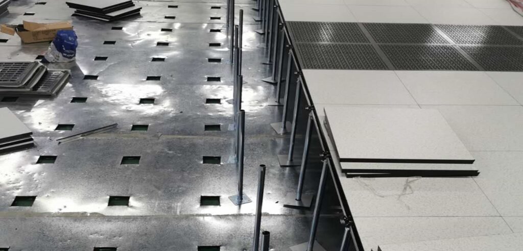
Bracket Installation:
Securely anchor bracket bases to the floor using expansion bolts or chemical anchors.
Leveling: Using a laser level or spirit level, adjust the height nuts on each bracket from a reference point in one corner of the room (typically a corner with a door). Ensure the entire top surface of the bracket network is at the same horizontal level. This is the most critical step in the entire installation process.
Crossbeam Installation:
Snap crossbeams into the top slots of the supports and secure them firmly with screws or clips to form a stable, level grid framework. - Floor Panel Installation
Starting Point:
Begin installation from one corner of the room (e.g., the far end from the main entrance) or the centerline, gradually expanding outward. This approach helps control cumulative errors and ensures an aesthetically pleasing result.
Cutting & Finishing: Precisely measure and cut panels for irregular areas like walls, column bases, and equipment pedestals.
Cut edges must be smooth and burr-free, then sealed with moisture-proof treatment to prevent warping and dust release.
Secure trim areas with dedicated trim brackets and beams for structural integrity.
Perforated Flooring: For areas requiring underfloor air distribution, install ventilation flooring with perforation rates meeting design specifications. For cable exits, install dedicated cable exit panels or use specialized cable outlets. - Adherence to these requirements and precautions ensures the data center’s anti-static flooring system not only maintains an aesthetically pleasing appearance but also provides safe, stable, and long-term service to the facility’s equipment.